Manage area

On the Model tab, in the Manage group, the Manage area menu includes the following tools.
Set limits and save
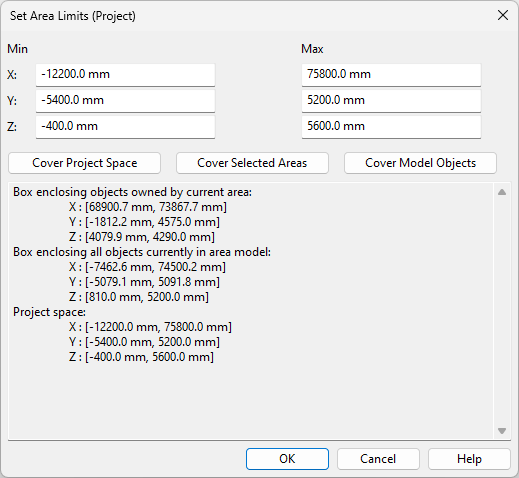
Select Model tab > Manage group > Manage area > Set limits and save to open the Set Area Limits dialog. This dialog automatically opens when you open a new Plant Modeller area for the first time. Here, you can set the size and location of your design area by adjusting its limits within the Project Space. The area limits determine which portion of the project space is visible to you, and whether your area overlaps with any other design areas, allowing them to receive updates from each other.
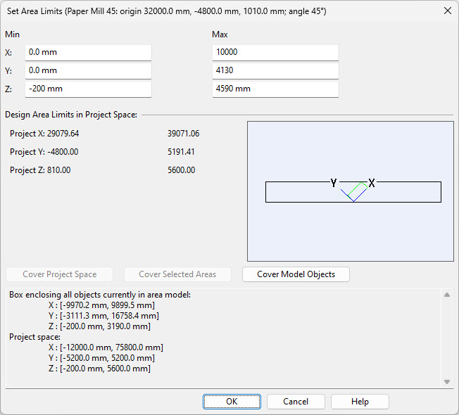
The title bar of this dialog displays the name of the design area's coordinate system in parentheses. The non-rotated root coordinate system, which the project space also utilizes, is named 'Project'.
For areas using Local coordinate systems, the title bar also displays the coordinates of the origin point and the (counter-clockwise) rotation of the area.
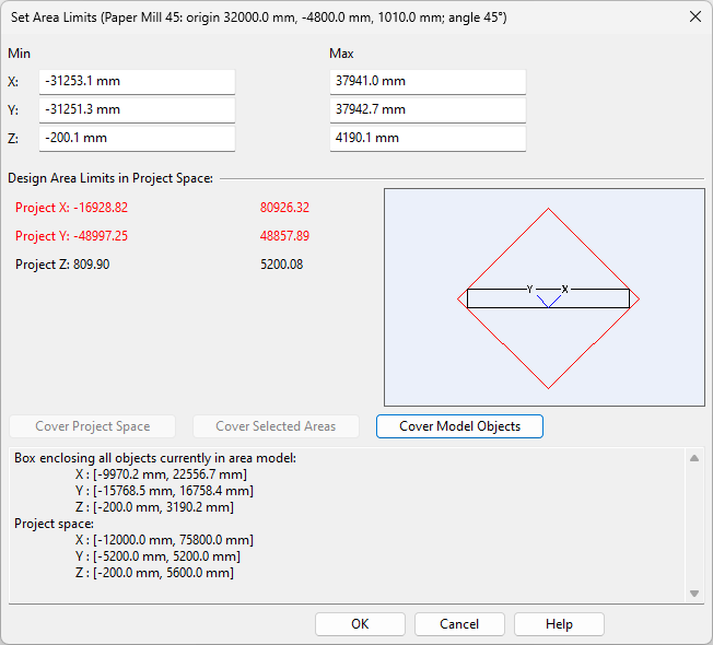
You can change the area limits anytime, but if any objects are currently checked out to you, they must fit within the new limits. To set new limits, enter the required coordinate values in the Min/Max fields, or click one of the Cover… buttons described below. A red color indicates that the resulting design area would exceed the project's limits. If this happens, you must either make the design area smaller, or ask the project administrator to expand the project space.
-
Cover Project Space – This sets the area's limits to be the same as the project's limits. This is mandatory for using the cable router in the area. The button is disabled if your design area uses a local coordinate system.
-
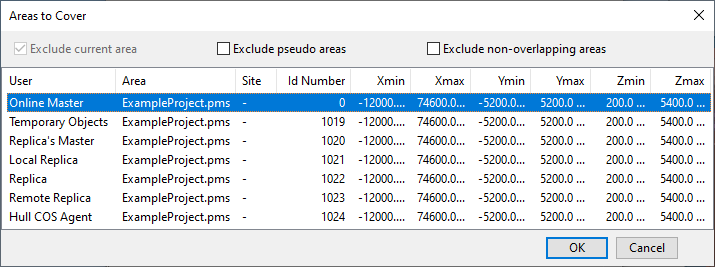
Cover Selected Areas – This enables you to set the area's limits by selecting one or more other Plant Modeller areas from the Areas to Cover dialog. The button is disabled if your design area uses a local coordinate system.
-
Cover Model Objects – This sets the area's limits around all the objects that currently exist in the project. If using a local coordinate system that includes rotation, the resulting area likely exceeds the project's limits, requiring you to adjust the values manually.
Note: If you are working on a satellite site where a document mask box applies, you can choose one of the replication pass boxes that the master site has defined for your site. See Set Mask Box.
In the case of a local coordinate system, the design area limits are adjusted along the main axes of the given coordinate system. In the Design Area Limits in Project Space section, Project X, Project Y, and Project Z display the corresponding min/max values in the 'Project' coordinate system.
To accept and save the new limits, click OK. After this, the other design areas in the project are aware of your new design area limits.
Set model area access rights and save
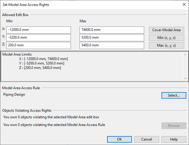
Select Model tab > Manage group > Manage area > Set model area access rights and save to open the Set Model Area Access Rights dialog. Here, you can adjust your access right limits within the design area and select an access rule that further defines which object types you are allowed to modify in that area.
The dialog opens automatically when you start a new area for the first time and project administrator has enabled the use of access rights in that project. If the dialog does not open automatically, and trying to open it from the menu shows the message 'Access rights not in use', then the project administrator has not enabled the relevant option as described in Area Model.
When access rights are in use, the program checks for access right violations when an operation is about to change an object's ownership or save it in COS. For example:
- When you Check out or Check in objects.
- When you Request or Relinquish object ownership.
- When you are Saving the area model.
Define the access rights to be used as described below.
Allowed Edit Box
You can adjust the XYZ limits of your editing area either manually or by using the following buttons:
- Cover Model Area – Select this to set the coordinates so that you can edit the entire model area.
- Min (x, y, z) – Select this to pick the minimum corner of the edit box from the model.
- Max (x, y, z) – Select this to pick the maximum corner of the edit box from the model.
Model Area Access Rule
You can select an access rule by clicking Select. Administrator defines these rules, as described in Access rights.
Objects Violating Access Rights
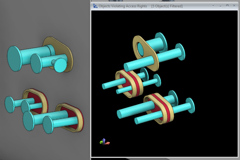
This section shows the number of objects that you currently own (that are checked out to you) but cannot modify because they are not completely inside the allowed edit box or do not match the access rule. If there are such objects, you cannot click OK to accept the current settings. Instead, click Browse to open the Objects Violating Access Rights view—this view shows the conflicting objects and it stays open if you close the access rights editor, allowing you to easily select the conflicting objects for check-in.
If you have adjusted the edit box limits or selected an access rule and there are no conflicts, click OK to use the new settings.
You can check which access rule each design area is using, as described in Show model area properties.
Set header attributes and save
Select Model tab > Manage group > Manage area > Set header attributes and save to set the header attributes used by documents and save the model.
Area properties
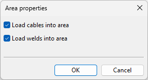
Select Model tab > Manage group > Manage area > Area properties to modify the area properties. Changing the properties may require that the area model is cleared and reloaded from COS.
-
Load cables into area – If selected, cables are loaded into the area model and you will be able to perform cable routing in the area.
Clearing this option will prevent you from using the tools in the Cables group of the Cabling tab.
Note: To use the Cable Router, the design area must cover the whole project space.
-
Load welds into area – If selected, welds are loaded into the area model and you will be able to perform weld-related operations in the area.
Clearing this option will remove the Weld tab from the Plant Modeller ribbon.
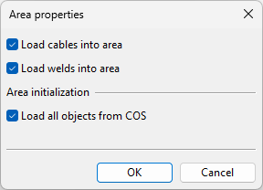
When first opening a new area, the dialog has an additional option:
-
Load all objects from COS – If selected, all model objects are automatically loaded from COS. Otherwise, you must use Load updates to load them.
Rebuild
Select Model tab > Manage group > Manage area > Rebuild to rebuild the model area as it is. This may help, for example, in situations where the program has replaced corrupted object geometries with temporary objects.
Check for objects outside area limits
Select Model tab > Manage group > Manage area > Check for objects outside area limits to check if you have checked-out objects that are outside your area limits. The program reports if such objects are found and you can select how to proceed. This check is performed automatically every time you start Plant Modeller, but you can run it manually anytime.
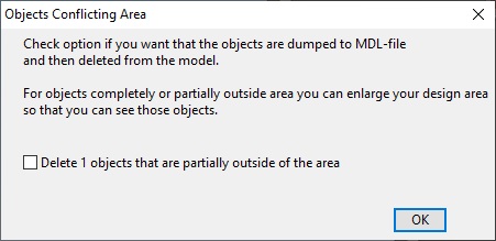
Select how to proceed:
- If you select the Delete checkbox and click OK, you are prompted to save the conflicting objects in an .mdl file, and then the objects are deleted from the model.
- If you just click OK, the objects are not deleted from the model. You must enlarge your design area, if possible, if you want to see the conflicting objects.
Check for duplicate objects
Select Model tab > Manage group > Manage area > Check for duplicate objects to check whether the model contains any duplicate objects—that is, two or more instances of the same object in exactly the same location. You should remove the additional items, keeping only one instance of each, before creating material listings. This check is performed automatically every time you start Plant Modeller, but you can run it manually anytime.
If you run the command and nothing happens, no duplicates were found. If it does find duplicates, the Check Duplicates dialog opens listing the locations where duplicate objects exist, and a separate Show duplicate objects view opens showing the currently selected objects.
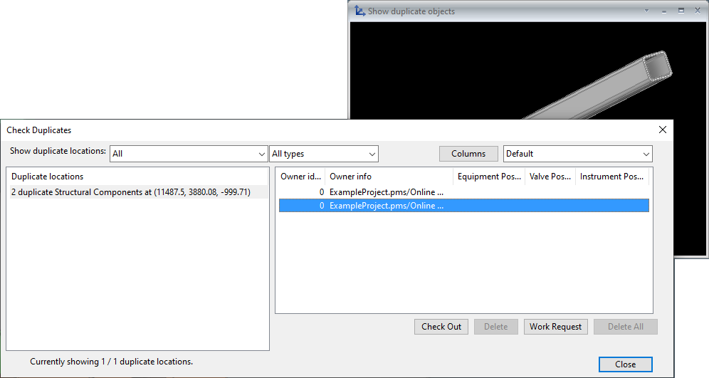
In the Show duplicate locations settings, you can filter the list of duplicates by selecting to show only objects that are checked out to you, or by selecting to show only objects of specific type.
In the left pane, select a location to list the duplicates in that location. Then, in the right pane, select one or more duplicate objects to manage them with these tools:
- Check Out – Checks out the selected objects, if possible.
- Delete – Deletes the selected objects, if possible.
- Work Request – Opens the New Work Request dialog for requesting the removal of a duplicate object that is owned by somebody else.
- Delete All – Deletes all listed objects, if possible.
When you have removed all extra objects from a specific location, that location is no longer listed in the Duplicate locations pane.
After closing the Check Duplicates dialog, you can still use the Undo command in the Quick access toolbar to restore the deleted objects, if needed.
Update and sync service spaces
Select Model tab > Manage group > Manage area > Update and sync service spaces to update the model area and synchronize Service Spaces. This command performs the same actions that are automatically performed during every start-up, as described in Synchronization of service spaces.
Clear model and save
Select Model tab > Manage group > Manage area > Clear model and save to clear the model. This can have the following consequences:
- If the P&ID module is used as a linked application, all objects that are owned by the current design area will be disassociated from the P&I databases. This may take some time.
- The component model library is emptied, and components will be inserted back to the library upon demand.
You are prompted if there are unsaved changes—selecting Update & Clear saves those changes to COS.
After using this command, you can use Load updates to reload the objects to your design area.
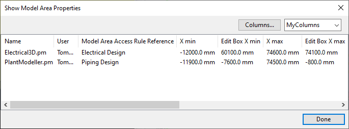
Show model area properties
Select Model tab > Manage group > Manage area > Show model area properties to open the Show Model Area Properties dialog.
In this dialog, you can see the name of the model area and the user, the area limits, the edit box limits, and the model area access rule (if in use). Columns that show the area ID and parent site's name are not shown by default. Click Columns if you want to add or remove columns or change their order.
This list can be exported to a Microsoft Excel file, as described in Export data tables to Microsoft Excel.